

Path Planning for Truss Robots
|
In this project, I investigated how to control a truss robot in a way that maximizes the network’s stiffness to gravitational forces and minimizes control input. This could have implications on the load carrying ability of the network, disturbance rejection during locomotion, and ability to assume certain target configurations. I identified two problems that are relevant.
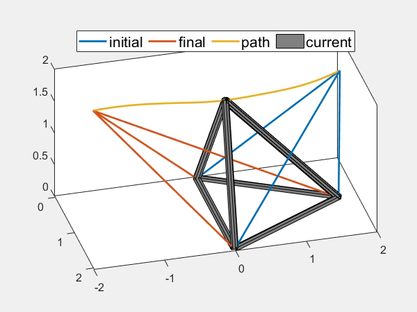
The first is moving the network from one configuration to another under an optimal control policy. Using a calculus of variations approach, I was able to construct a Hamiltonian which is comprised of the system dynamics and two penalties. The first penalty is the expected deflection due to gravity and the second is the joint torques necessary for the desired motion. A two point boundary value problem is solved to find the optimal control policy. Notice that the computed paths are not simply straight lines between the final and initial states. The path rather takes the robot into configurations that distribute the gravitational load among its members. The second problem is to select an optimal configuration the network should assume for tipping, which enables the robot to locomote via punctuated rolling locomotion. I solve an optimization over the robot state to minimize the forces in the members due to unit deformation in the direction normal to the tipping face subject to constraints on the robot kinematics and geometry. I also implemented an RRT* method to solve the control problem. This approach allows us to apply physical constraints of the robot kinematics and geometry and avoid obstacles that may be in the robot's environment. |
Tetrahedral truss robot follows optimal path to tipping configuration.
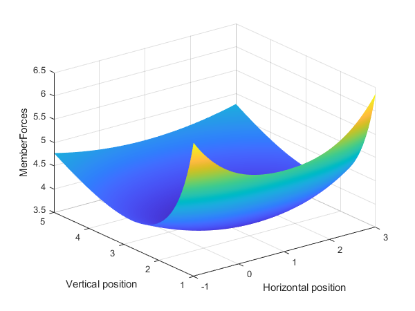
Norm of the member forces in the impact configuration as a function of the position of the free node at tipping. The minimum of this surface is the desired tipping configuration.
RRT* method to move into tipping configuration while respecting non-convex constraints and avoiding obstacles.
|
Maze Exploring Turtlebot
|
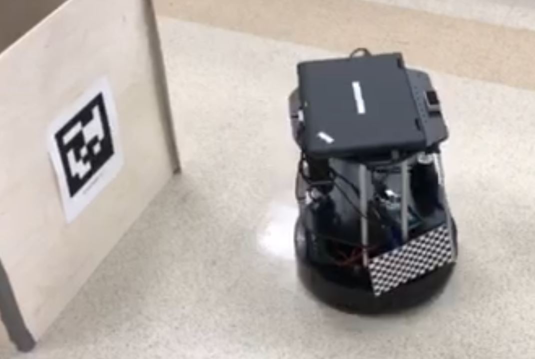
In this group project, my team programmed a turtlebot to explore a maze and visit a number of places of interest in a given sequence. To start, the robot explored the maze under human direction while building a map and identifying the locations of QR tags. When all of the QR tags were identified, the robot received a message containing which QR tags should be visited. The robot then drove autonomously using an A* path planner and a lower level path tracking controller to visit each tag in a given order. Unfortunately, we did not take any video during the demo, but I do have a video during a test.
|
|
3D Printing
|
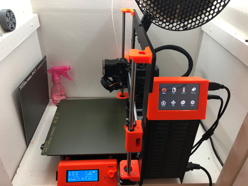
I have assembled a few 3D printers including a Prusa i3 MK3s, Ender 3, and an Anet A8. I have enjoyed designing a number of modifications for these printers to improve the print quality and user interface including a wifi enabled touch screen, a print head endoscope, and belt tensioners. I have also printed some interesting objects like a tensegrity structure and a rattleback.
|
|
A Whole New Microcontroller!
|
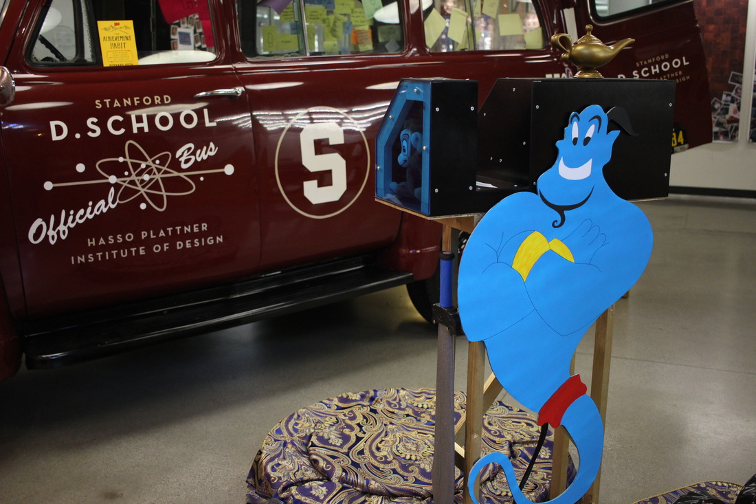
The project elevator pitch:
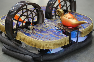
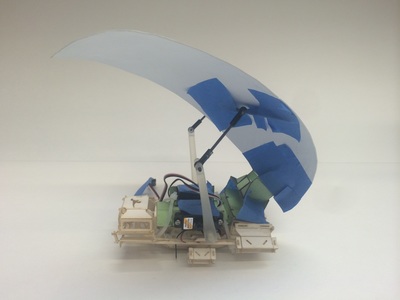
Build a hovercraft and a remote controller that communicate with each other over radio frequency in accordance with a class-defined communications protocol. Each team's hovercraft and remote controller must be interoperable with other teams' hovercrafts and remote controllers. These hovercrafts and controllers must be able to compete in a game of collecting ping pong balls into a goal. Every team selected a theme to design their hovercraft and controller. My team selected Aladdin's Magic Carpet for the theme so that we could control our hovercraft via flying carpet. To create this sensation we utilized suspended a drive platform using a trampoline. The platform is designed and fabricated such that the platform tilt, measured with an accelerometer, will correspond to the control input to the hovercraft. Fabric is placed over the platform to give the user the feeling of flying on a magic carpet ride. Our hovercraft, Prince Ali, glides along a thin film of air created with a hard, hockey puck style base. A pair of fans provide propulsion and steering. When it is active, a genie pops out of the lamp to indicate that the hovercraft is paired with a remote controller. The hovercraft is equipped with two enchanted scimitars that push ping pong balls. My primary responsibilities for this project included implementing the radio communication of the remote controller, construction of the genie and lamp on the hovercraft, capacitance touch measurement of the lamp on the remote controller, and music. For more information please see the project website: |

|
Jigsaw Coasters
|
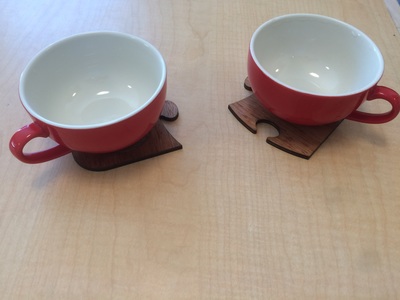
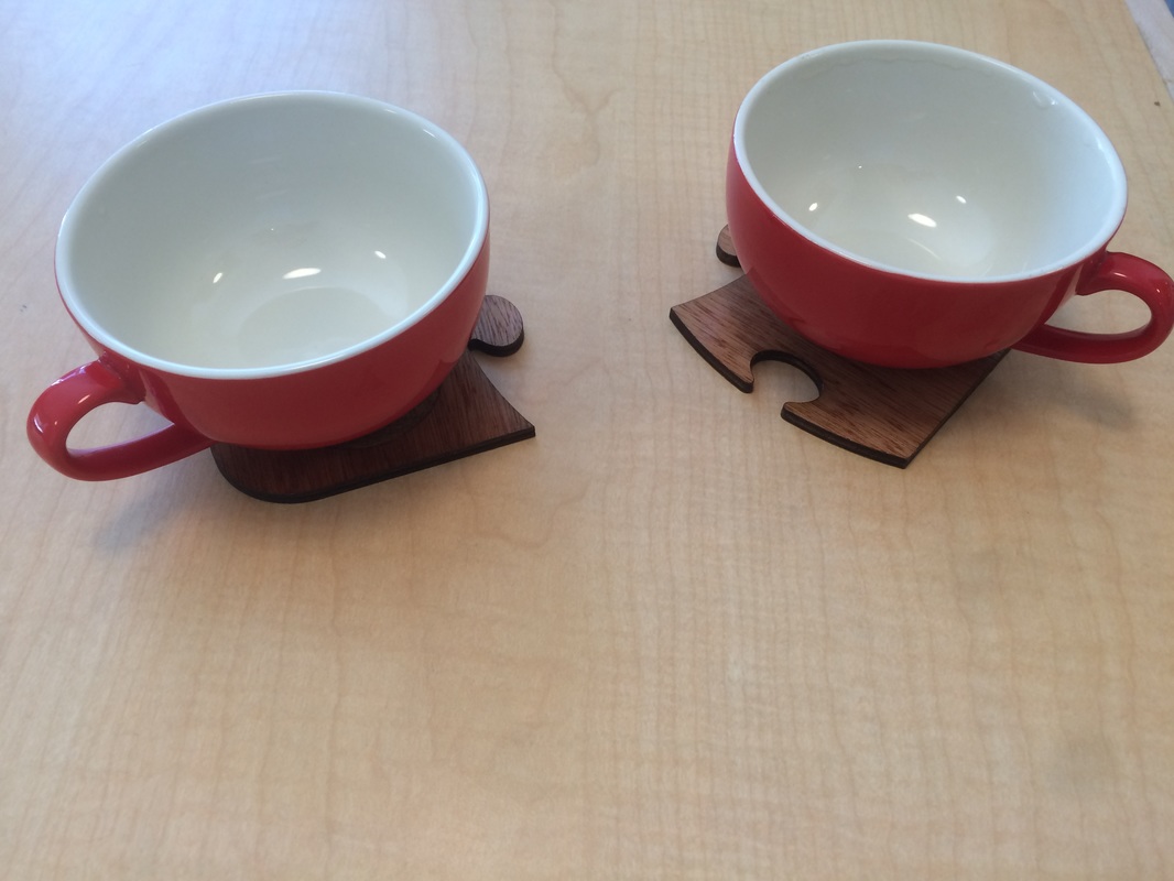
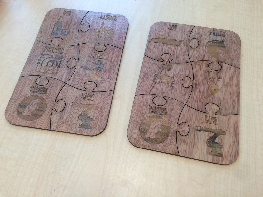
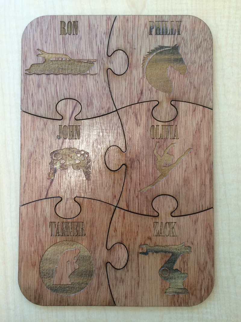
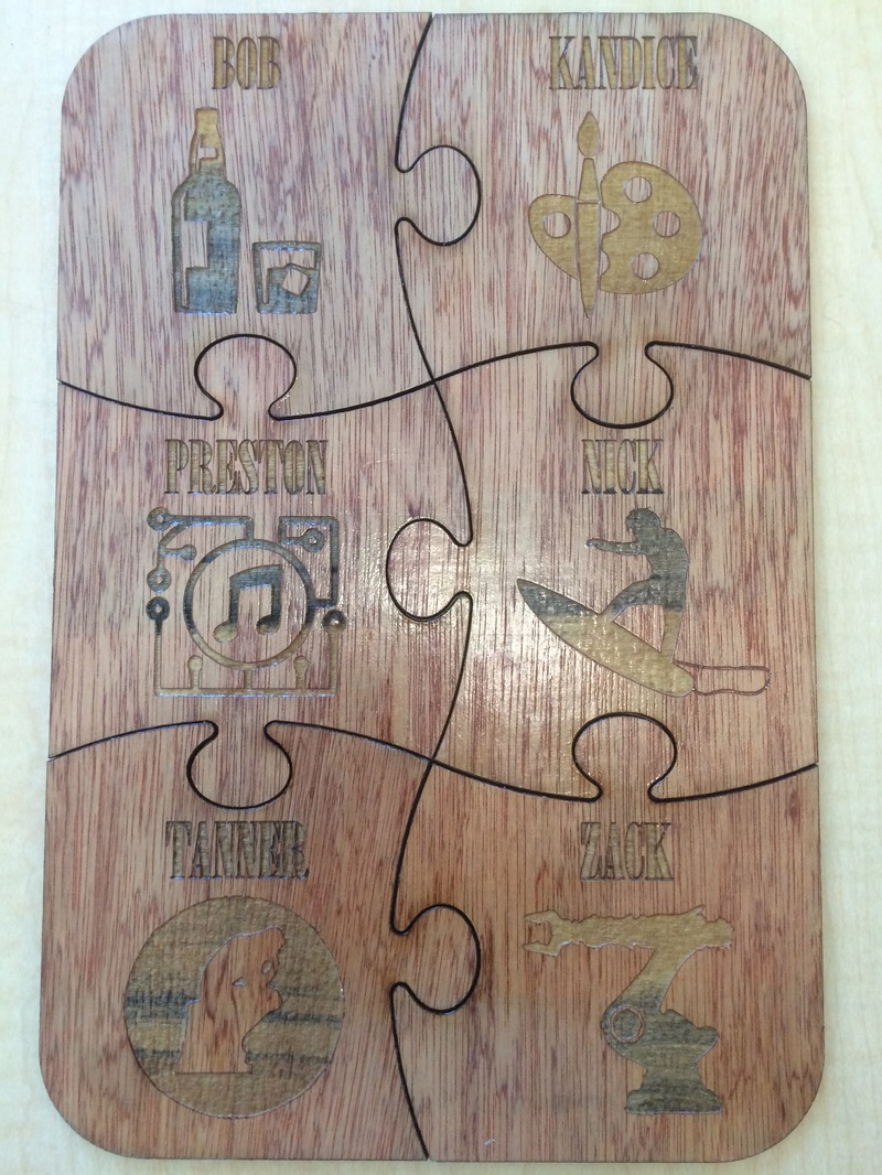
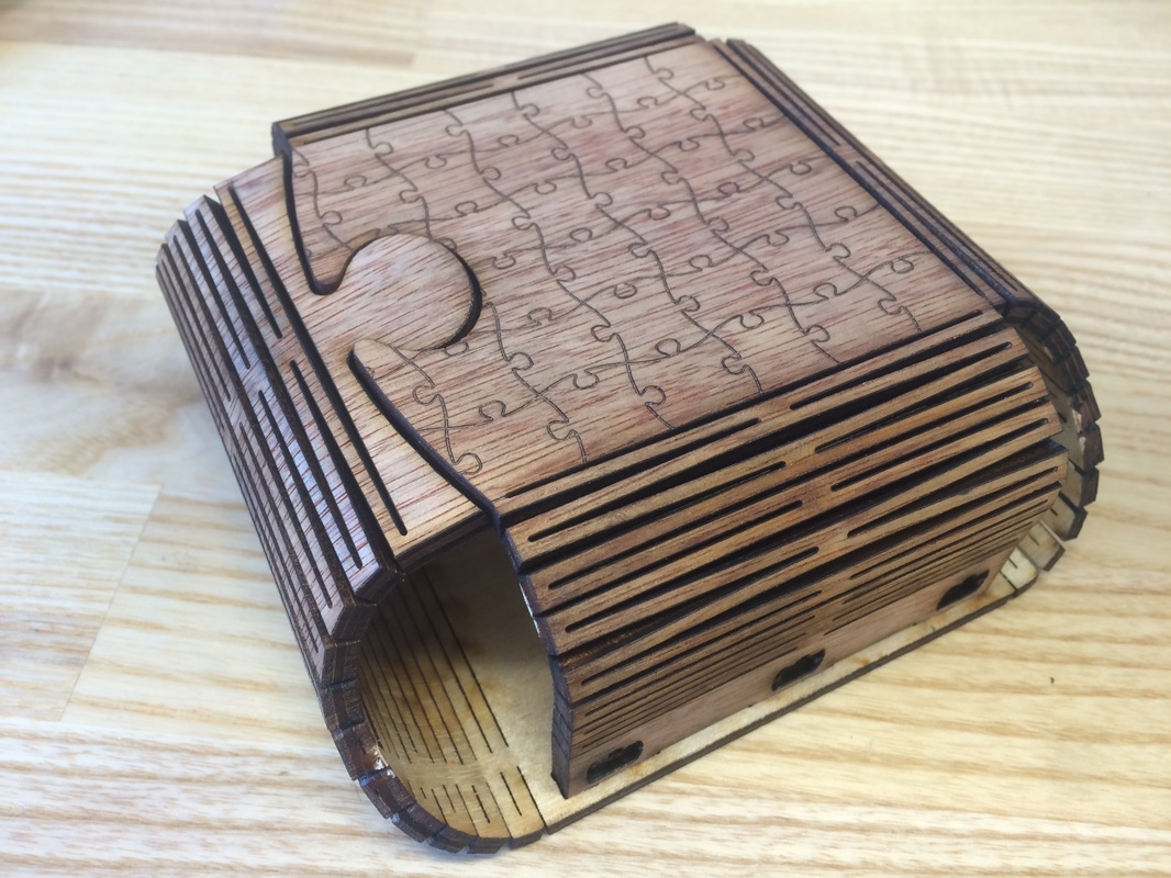
I made a couple sets of coasters that fit together like a jig saw puzzle as Father's day gifts. Each coaster includes an icon that represents a member of the family. I also formed a container for the coasters out of a single piece of plywood that folds at living hinges.
|
|
Mobile Robots for President!
|
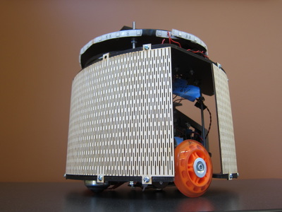
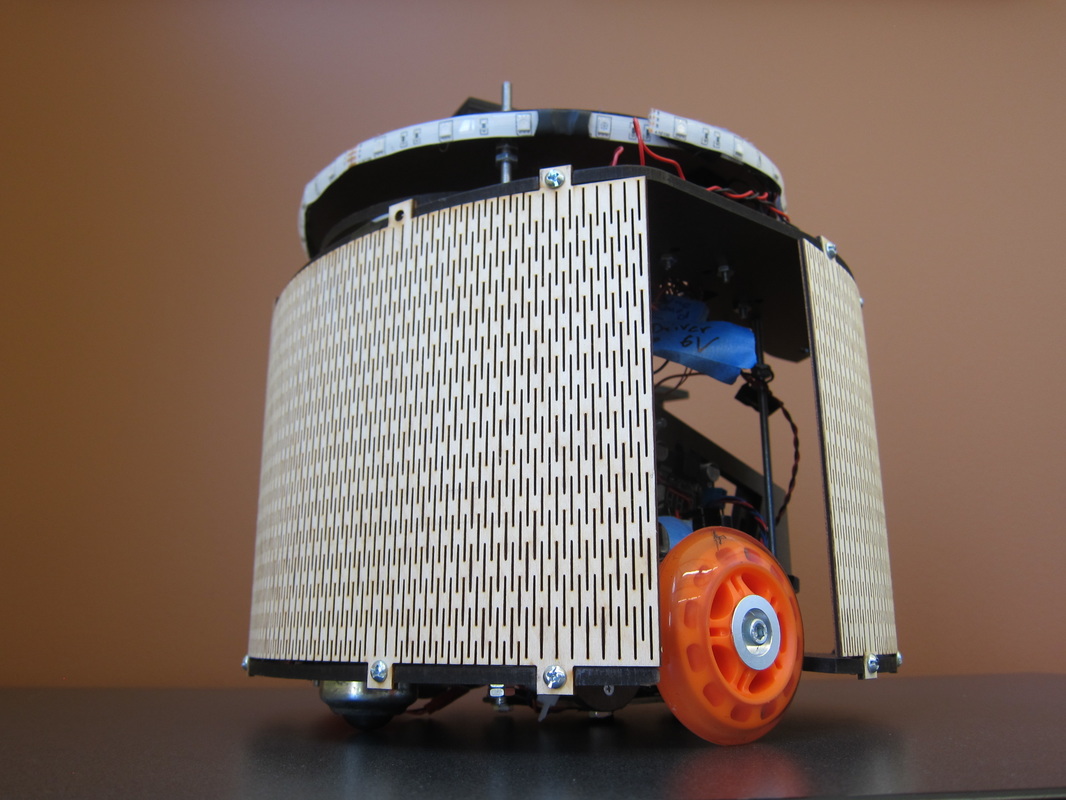
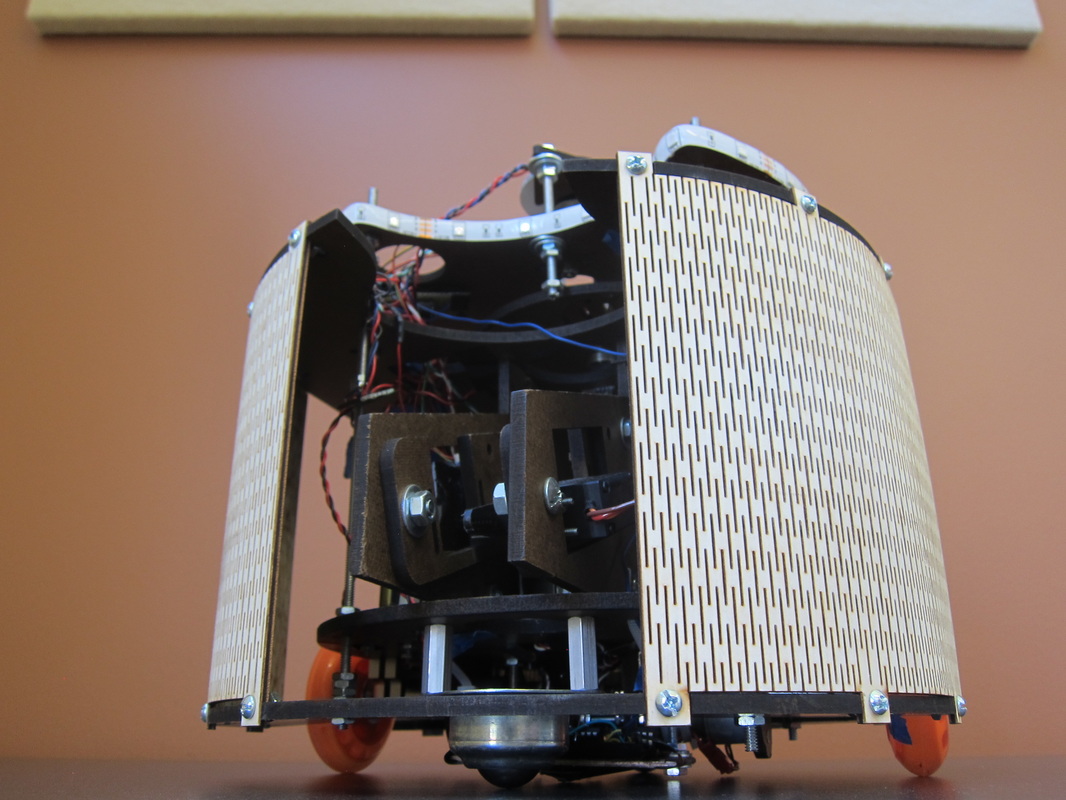
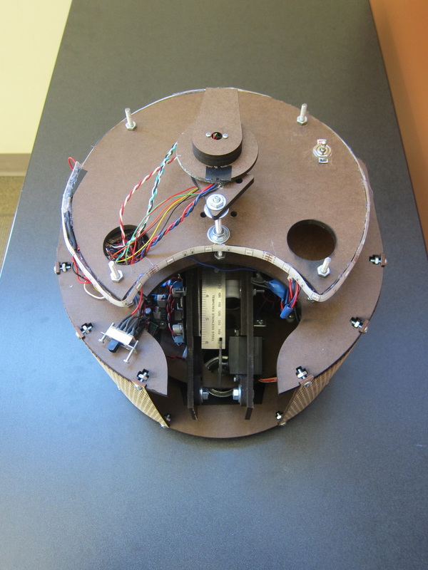
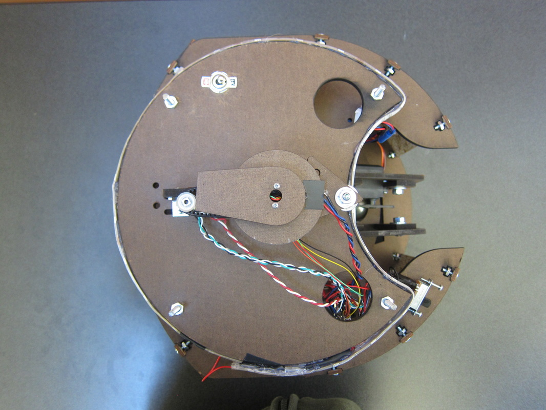
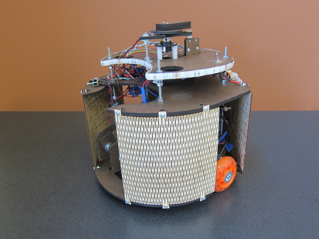
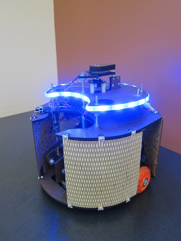
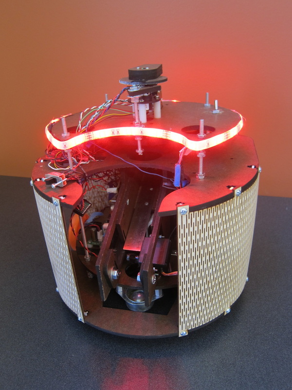
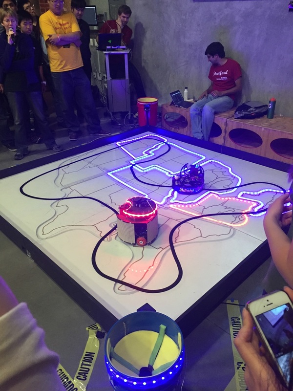
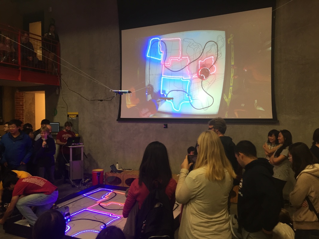
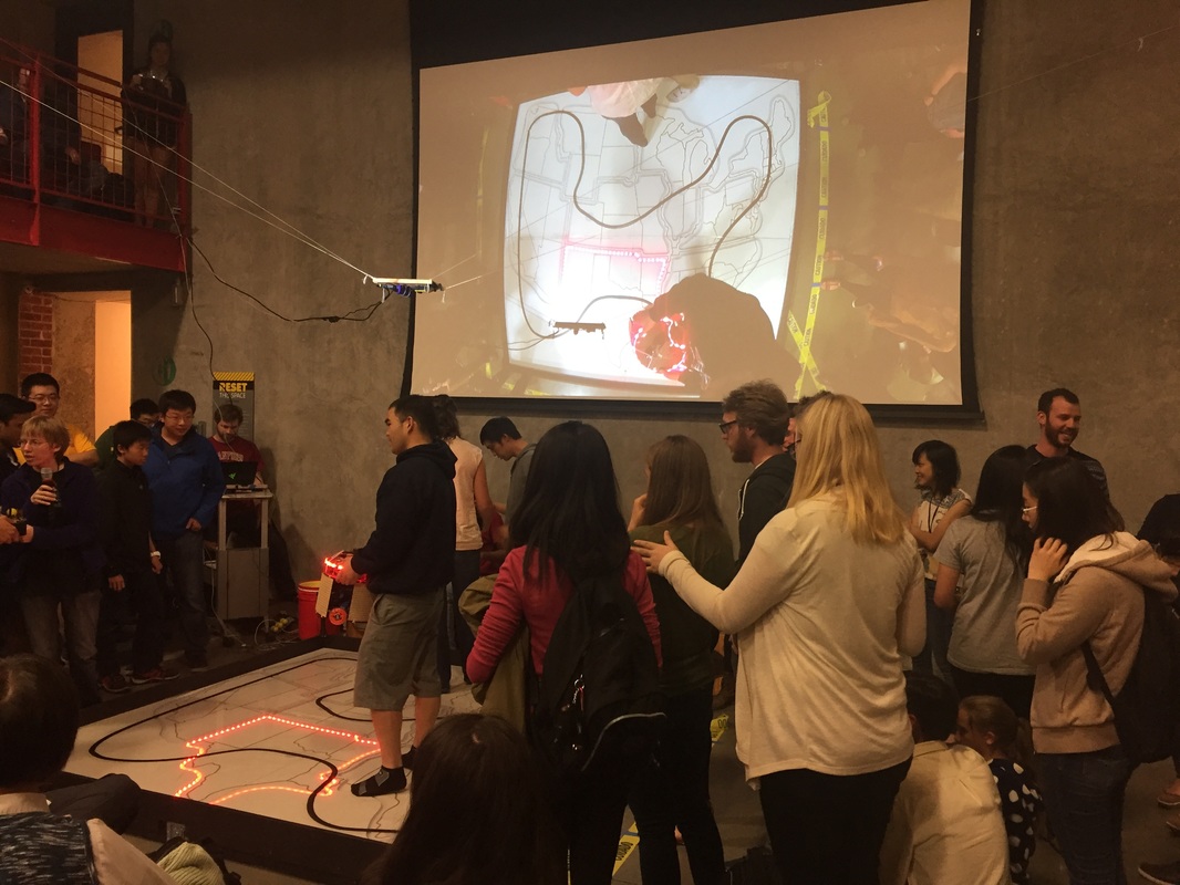
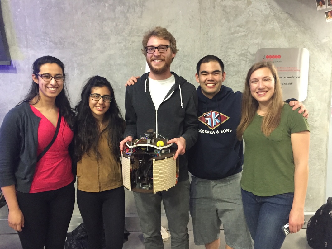
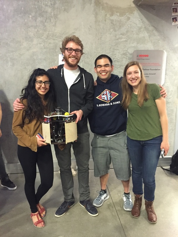
Two robots compete head-to-head to win the vote of the United States electorate before the end of the campaign season. The 8'x8' game board was shaped liked the United States and was divided into nine regions, each of which was encircled by an LED strip signifying the loyalty of that region. The goal of the game was to drive our robot to as many of these regions as possible and switch the LEDs in that region on to match our candidate's color. To switch the region to our loyalty, our robot had to take measurements of a pulsing electromagnetic field in a 2" region and communicate those measurements to the game controller over SPI. Additionally, at any point in the game, we could shoot a foam ball into a bucket located at a corner on the game board. This action was analogous to launching a political attack ad on our opponent, which caused their robot to lose some functionality for ten seconds. At the end of two minutes and eighteen seconds, the robot with the most loyal regions was pronounced the winner.
My primary responsibilities for this project included the triangulation of the robots location on the game board and the PID control of the robot's motion. |
|
Drought Diggers Arcade Game
|
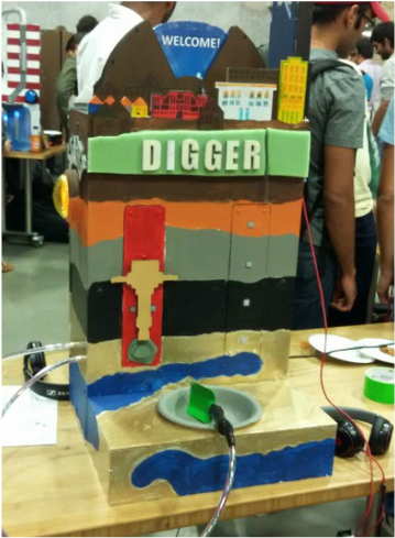
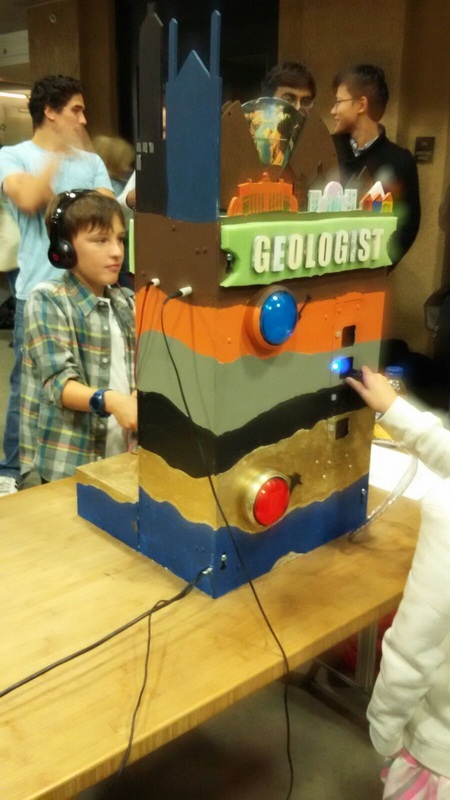
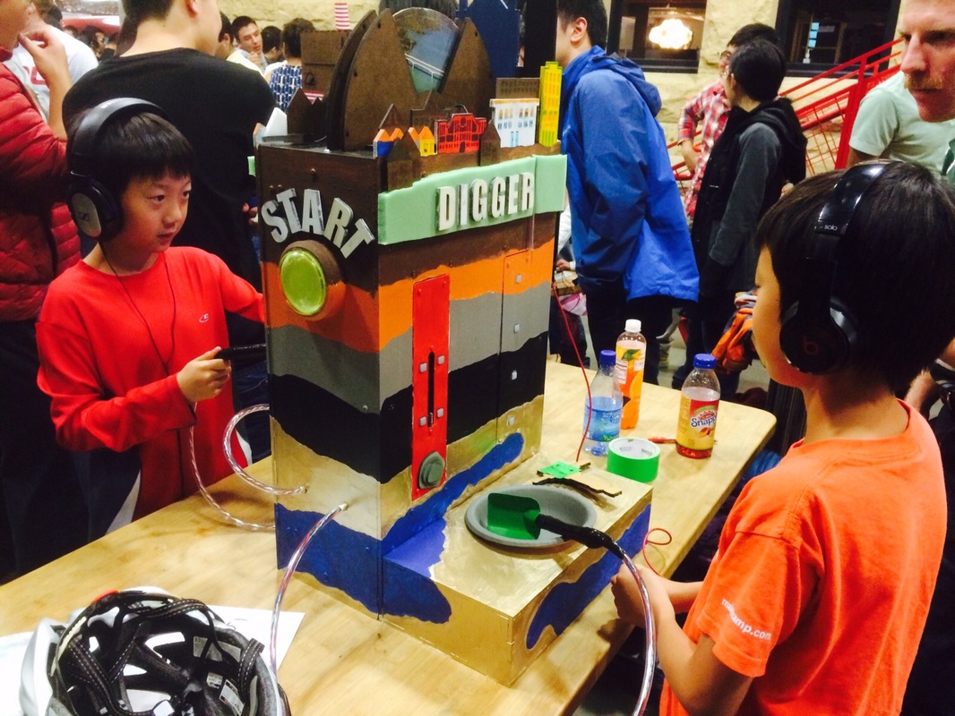
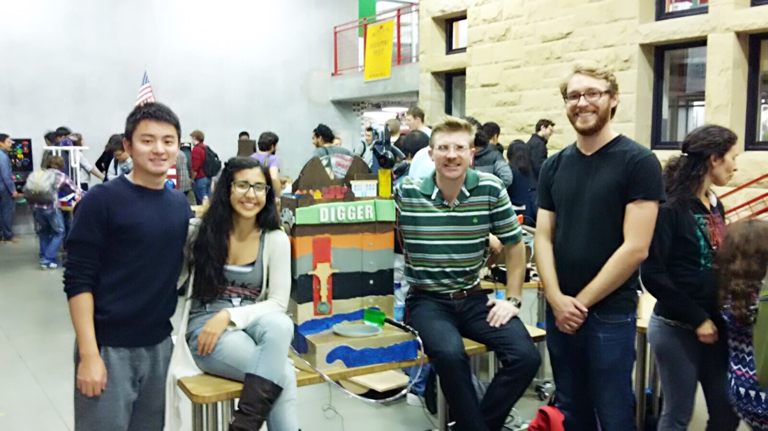
A Californian city is on the brink of chaos as their remaining reserves of water run dry. Their last bastion of hope lies within the ancient prophecies that tell of an aquifer that lies under the city. In a last ditch effort to save the city from complete anarchy, two heroes set off on an arduous journey to quench their thirst. The Geologist, equipped with a stratafyer, has the ability to study the soil and bedrock beneath the city. The Digger, ready to get his hands dirty, has the tools to get the job done. Only together can they save the city from complete destruction.
My responsibilities for this project included the mechanical design and fabrication of the arcade game, game audio, and the motion control software for the stepper motor that drove the timer wheel. |
|
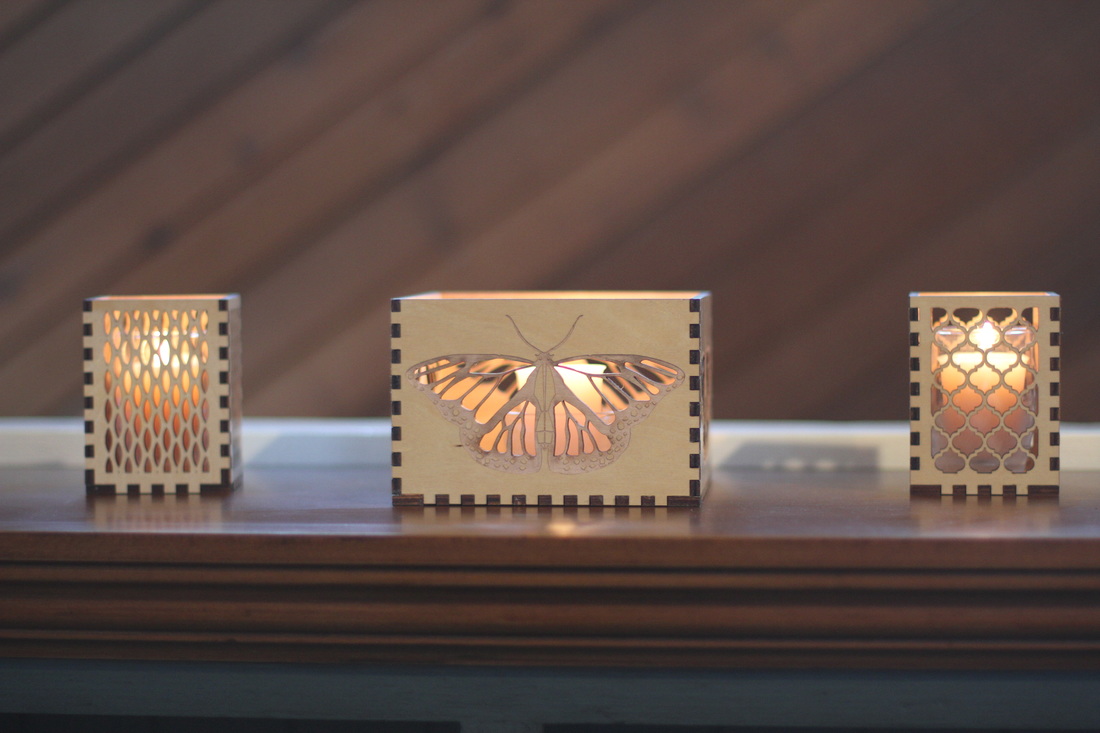
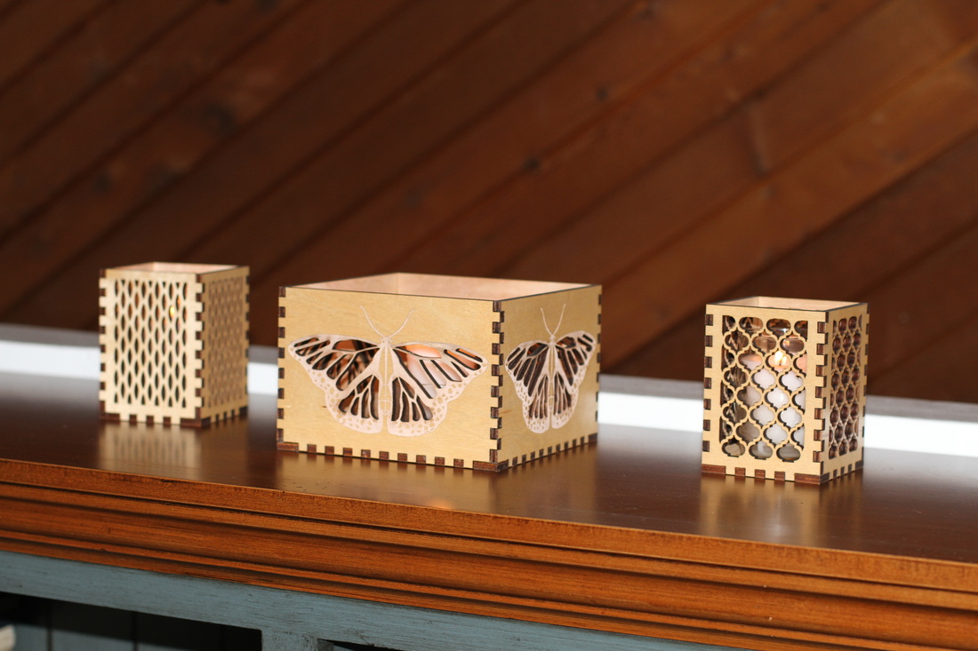
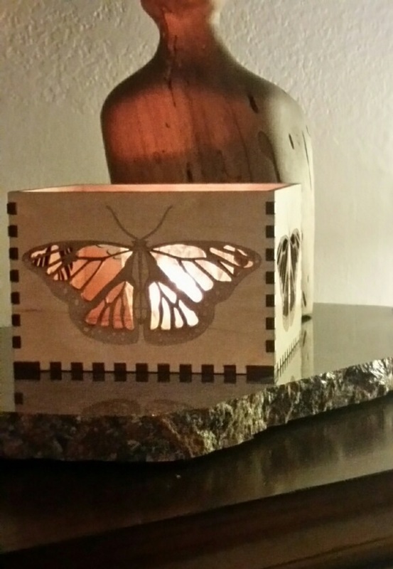
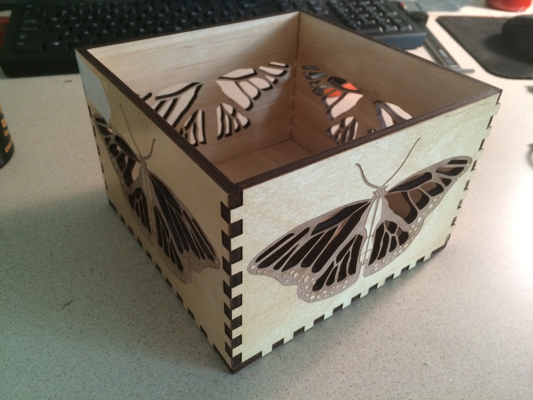
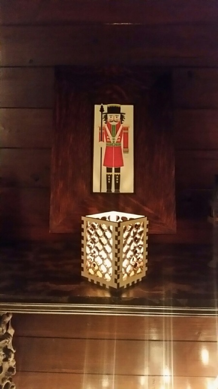
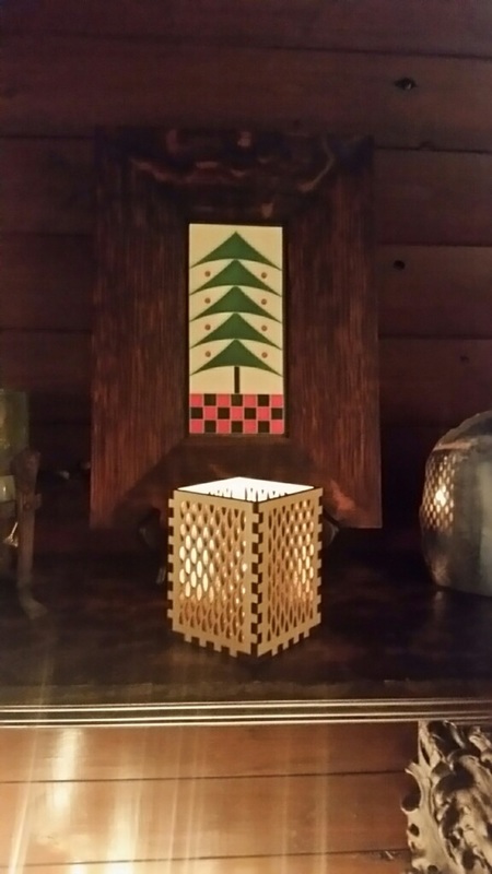
Laser Cut Candle Holders
For some personalized holiday presents I created my own candle holders. I cut, vector engraved, and raster engraved panels of birch with a CO2 laser to make the walls of the candle holders.
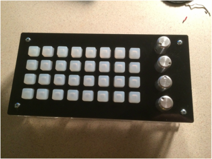
MIDI Controller
|
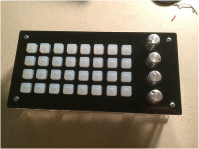
I programmed an arduino leonardo to communicate MIDI musical commands through serial communication to a PC. The controller queried the status of an LED button array via I2C serial communication to generate the musical notes and read analog voltages from four potentiometers to modulate tone and volume.
|
|
The Mothership
|
ASA has to date (2014) successfully explored the surface of Mars with robotic rovers including rovers named Spirit, Opportunity, and Curiosity. When exploring the surface of Mars, NASA’s past approach has been to send and deploy a single rover asset, and have the single rover explore the surface collecting data. While this approach has been moderately successful, as in the case of the rover Opportunity, it has also been marked with some failures. For example, the Spirit rover progressively lost wheel functionality, eventually becoming trapped in a sand dune, and was not recoverable. Current reports on the Curiosity rover suggest that its degrading wheels may also cause it to become immobile. With the cost of each Mars landing being astronomically high, the loss of the single asset is catastrophic to the mission. This causes NASA to be understandably cautious and to limit the rover's range and extent of movement to minimize risk.
The potential benefits of minimizing risk to a Mars asset is one of our motivations to create what we have termed the Mothership. The Mothership is designed to be a stationary Mars base asset that will assemble modular mission rovers to perform planetary surface exploration. Interplanetary communications, instrumentation, and significant power systems would all be anchored to a preselected ideal surface location while all specimen collection would be accomplished by small, lower cost, mobile rover platforms. Should any of the smaller mobile assets be damaged or lost, overall functionality of the Mothership would only be marginally diminished. |

|
For this project, our initial goal is to develop the proof of concept design of the Mothership or, as we like to call it, the robot that constructs a robot. The Mothership will assemble a small, initially disassembled rover unit that has the capability to leave and then return to be disassembled.
Though our initial goal is for the assembly/disassembly of a single rover unit with limited functionality, further development of the project would lead to more advanced capabilities. Storage of multiple units, mission modular components, and a more sophisticated user interface are all features that could be added given enough development time and resources.
I was responsible for leading the software team, coding in python (computer side) and C++ (arduino side), and synthesizing the devices with the Robot Operating System.
Controlled Kinematic Robot
|
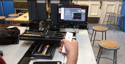
As we progress into the mobile computing age, we’ve found that there are more and more applications for technology allowing humans to interact with machinery. Everything from using a computer to controlling laboratory equipment requires some sort of human-machine interface. Many of these interfaces are complex and require significant training to operate or lack intuition and full immersion of the users senses.
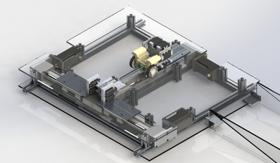
When we developed the Controlled Kinematic Robot (CKR), our objective was to create a robotic interface that was intuitive and easy for anyone to understand. The CKR is a multitasking, multiprocessor, user interactive robot. We designed the machine component using two Lowboy 760 direct drive stages mounted orthogonally to allow travel in a flat XY plane. The stages are controlled using a Nintendo Wiimote via a custom Labview virtual instrument. The virtual instrument was running on a host computer, and separate Labview virtual instruments controlled a NI Single Board Rio and NI FPGA. Use of the Wiimote allows us to control the stages in three ways, and we implemented a fourth control method through the host computer itself. The practical applications for this kind of technology are far reaching. Bomb disposal, remote surgery, or control in an inhospitable environment are all examples of situations where a human must be in control of a machine, but can’t physically be present. In many of these cases the human must remain in the loop to allow for dynamic precision control of the system. A direct, “natural” feeling method of control allows the user to smoothly operate and maintain control over their system. For this project I was responsible for developing the top level state-machine, the communication between the computer and each of the Single Board RIOs that control the stages, and the stage control algorithm. |
|
Cockroach-Inspired Self-Righting Robots
|
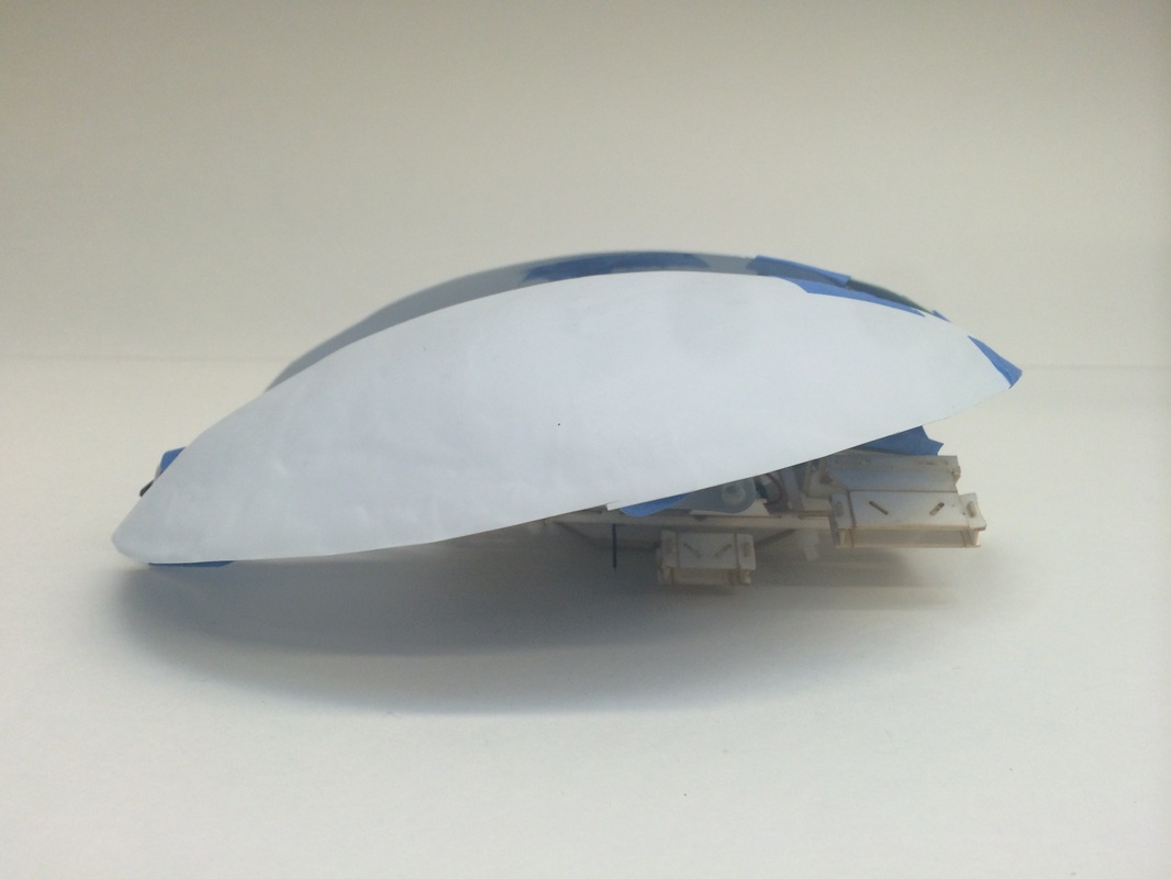
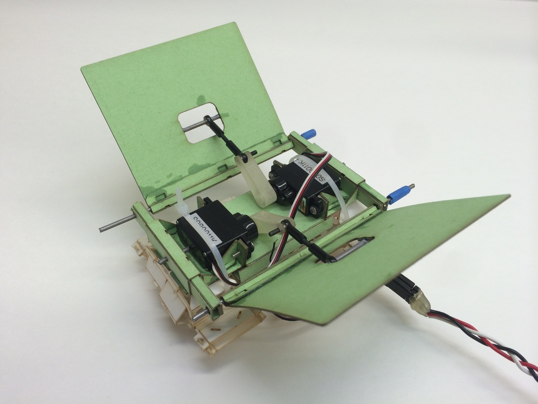
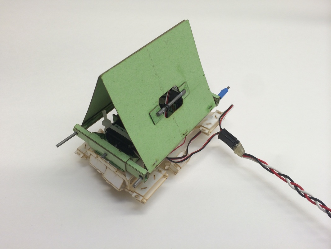
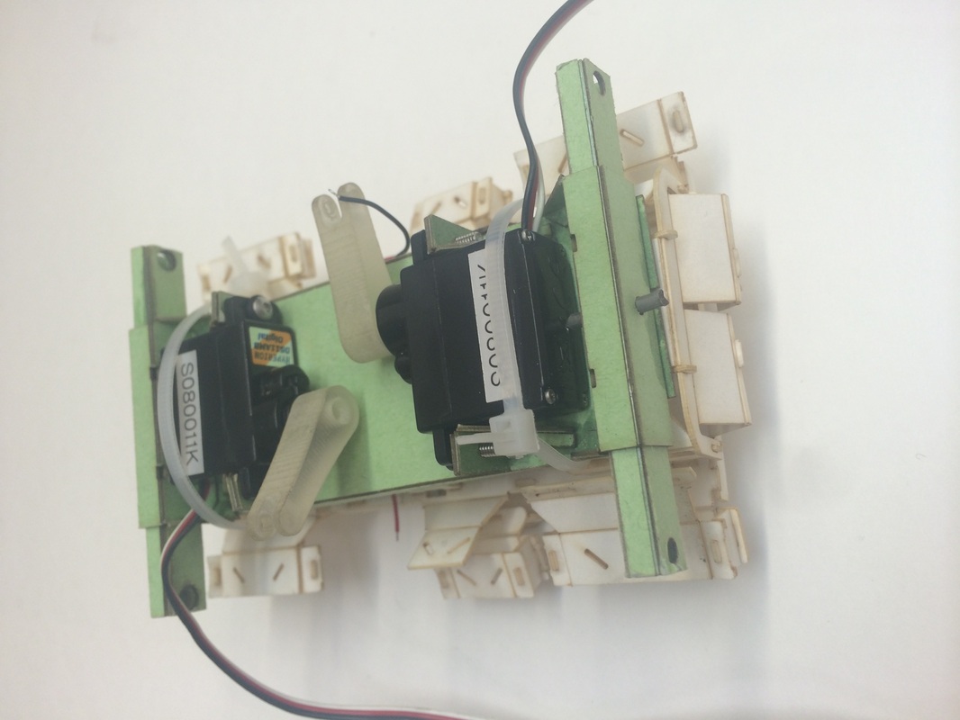
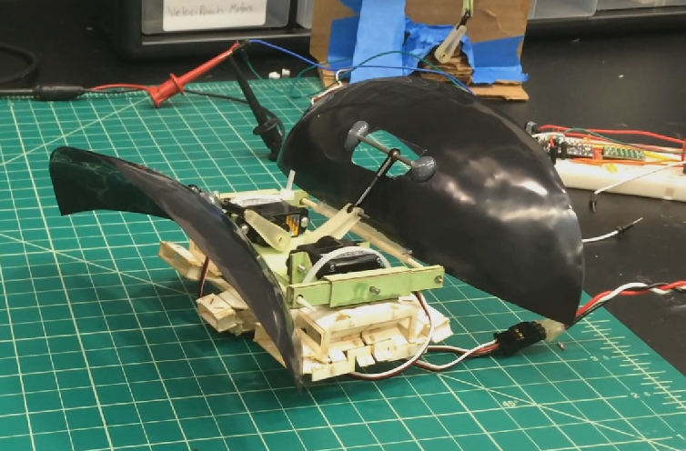
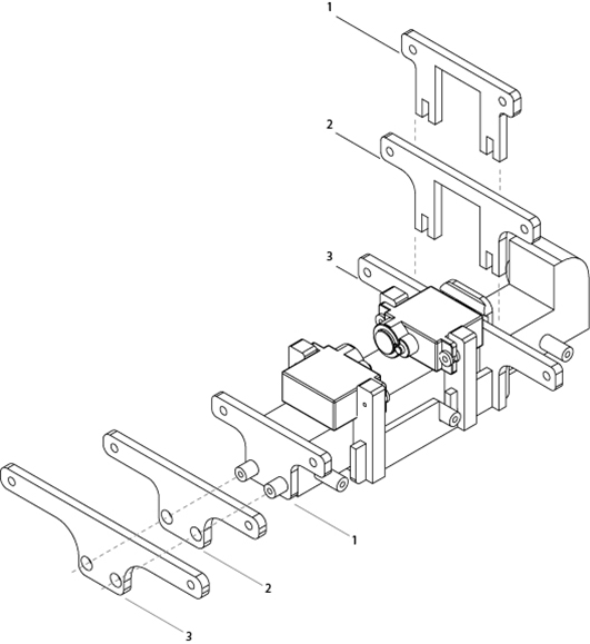
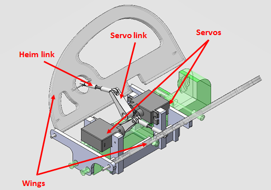
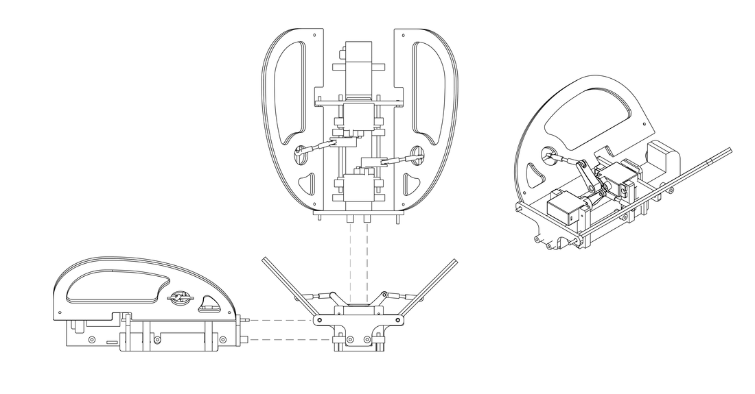
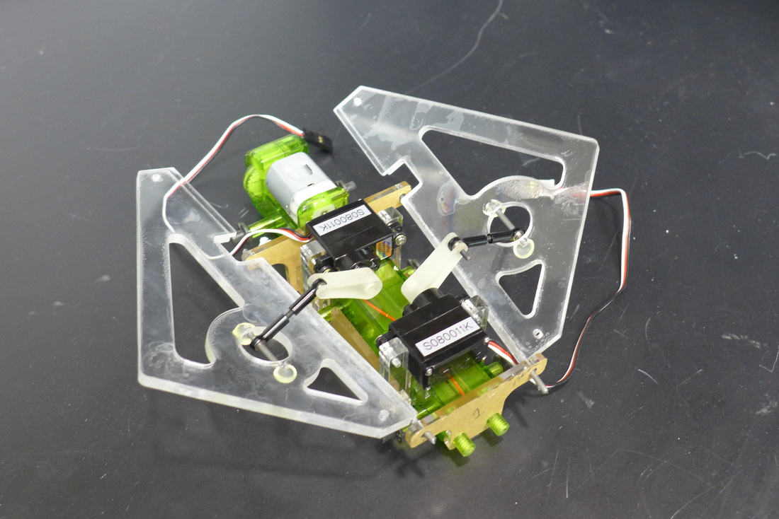
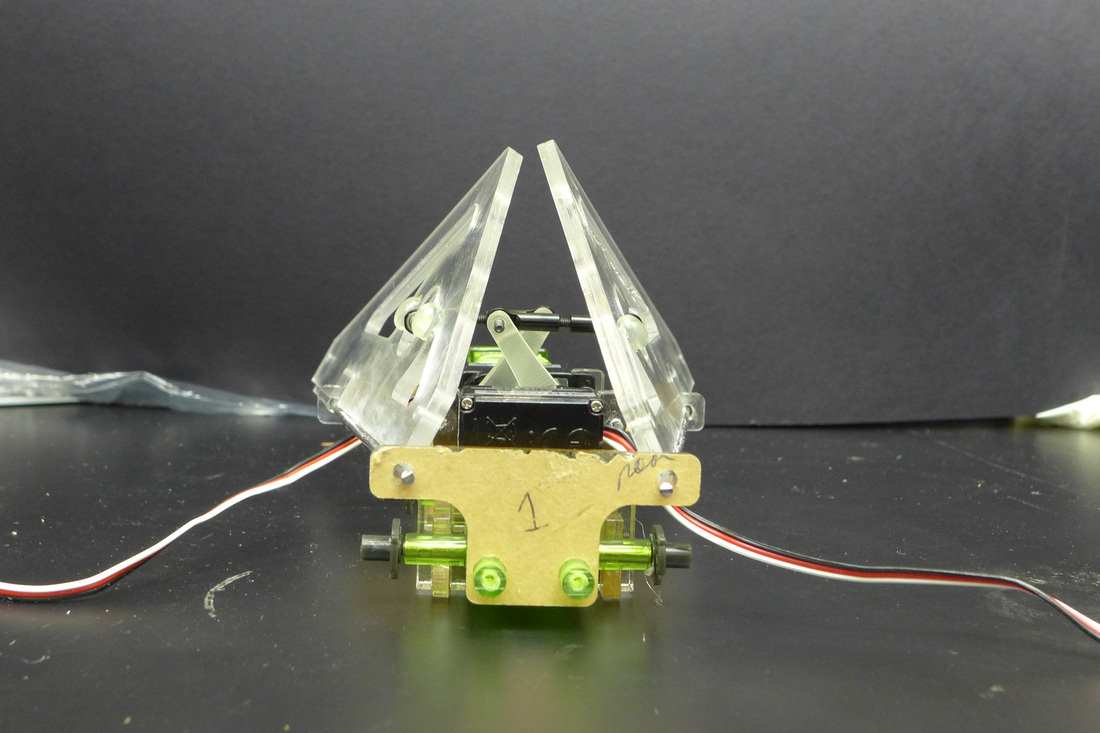
As an undergraduate researcher in the Poly-PEDAL (Performance, Energetics, Dynamics, Animal, Locomotion) laboratory, I worked with a team of researchers who are interested in studying the righting reflexes of animals and applying these righting strategies to robotic systems. Small scale robots have broad applications in search and rescue, reconnaissance, and environmental monitoring. Without a mechanism for correcting their orientation when they become inverted, these small robots cannot be deployed in rugged environments. My research partner and I collaborate to construct and test robots that mimic the righting strategies of a winged cockroach, one of the most versatile insects.
I have built small robotic models that mimic the righting strategies of the cockroach. The robots have a Smart Composite Microstructure body equipped with microprocessors, sensors, and actuators. These robots were designed with modularity in mind to enable us to study the effects of various parameters including wing shape, wing orientation, wing retraction, and actuation speed. |
|

Self-Erecting Inverted Pendulum
|
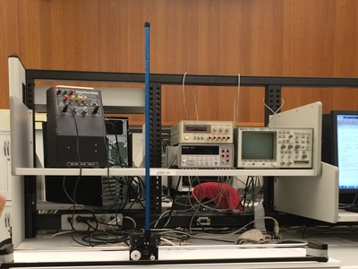
The pole-placement method was used to develop a controller to balance an inverted pendulum. This initial inverted pendulum system was not fully observable as the linear velocity of the cart and the angular velocity of the pendulum could not be directly measured. To address this issue, we designed a full-state Luenberger observer to estimate the entire state for full-state feedback control of the pendulum. This controller proved to be preferred over the previous controller because it was much less susceptible to noise. This prevented the controller from saturating the actuator and producing high torques on the gears. After the implementation of the observer, we designed a full-state feedback controller using the Linear Quadratic Regulator (LQR) design technique. Finally, a swing up controller was implemented such that the pendulum could erect itself. The swing up controller implemented the “energy pumping” method.
|
|
Magnetic Levitation
|
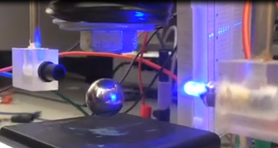
System identification, linearization, and circuitry component selection were performed to design an analog compensator to levitate a metal ball. The ball was levitated between an LED light source and a photo-resistor. The change in resistance of the photo-resistor in response to the metal ball occluding light from reaching the photo-resistor was used to measure the position of the ball. The compensator controlled the input current to the magnetic coil just above the reference point. Due to the high degree of non-linearity, the system was not robust to disturbances or model mismatch.
|
|
Poly-MUMPS Robot
|
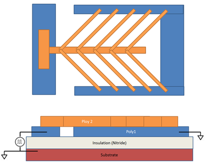
CHEVRON SHAPED THERMAL ACTUATORS FOR THE LOCOMOTION OF MICRO-ROBOTICS Excerpt from the design proposal: "Structure and Processes The proposed concept, illustrated in Figure 1, is referred to as the “caterpillar” because its method of locomotion resembles that of a caterpillar. The caterpillar consists of two polysilicon plates that are connected via an array of chevron shaped thermal actuators. The back end plate is connected to a power generator that produces a pulsed voltage signal. The front end plate is electrically grounded with the substrate. A layer of insulation between the caterpillar and the substrate keeps the plates electrically isolated from the substrate. The plates of the caterpillar are not bonded to the insulation layer. When the power source is high, the back end plate is acted upon by an electrostatic force that increases the apparent weight of this plate thereby increasing the static friction between this plate and the insulation layer. This increase in static friction effectively pins this plate in place. The front end plate which is grounded with the substrate does not feel an electrostatic force and is therefore relatively free to slide across the surface of the insulation layer. The potential difference of the two plates will drive current through the array of chevron shaped thermal actuators. The actuators will behave like resistors and dissipate energy as heat. The chevron shaped thermal actuators will expand in response to an increase in temperature and produce a displacement of the front end plate with respect to the back end plate, resulting in the caterpillar entering an extended state. (Figure 2, Panel B) |
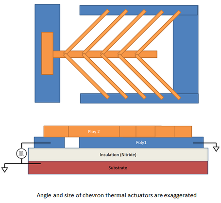
Figure 1. Diagram of proposed concept
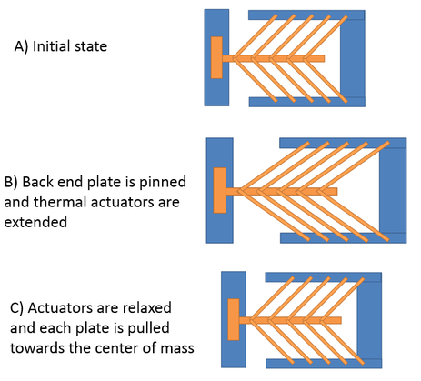
Figure 2. Process flow of locomotion
|
Once the caterpillar has reached its extended state, the power generator is turned off such that there is no potential difference between the two plates and the substrate. The back end plate is no longer affected by an electrostatic force and is now free to move. The absence of the current flowing through the chevron shaped thermal actuators causes them to cool and contract. This causes the back end plate to be pulled forward and the front end plate to be pulled backward. (Figure 2, Panel C) This results in a small net displacement from the beginning of the process flow. This process is then repeated to provide locomotion of the caterpillar. From the perspective of the back plate, there is no displacement when the battery is high and a small forward displacement when the battery goes from high to low. From the perspective of the front plate, there is a large forward displacement when the battery goes from low to high, and a small backwards displacement when the battery goes from high to low.
In the absence of friction, the center of mass would not move as the actuators contracted and the net displacement of the caterpillar would be equal to the displacement of the center of mass during the expansion of the thermal actuators. However, with the presence of external forces, the net displacement of the caterpillar is dependent on the relative coefficients of friction and masses of the two plates. Increasing the contact area and mass of the front end plate may increase the caterpillar’s ability to pull itself forward as the actuators contract but may hinder its ability to extend itself as the actuators extend. It should also be noted that the ability of the back end plate to adhere to the surface is an important limit in how fast the caterpillar can locomote. The force adhering the back end plate to the surface must be sufficiently large to ensure that the front end plate moves while the back end plate remains stationary.
The most likely means to supply power to the caterpillar is two compliant springs which electrically connect each plate to a pad. These pads can then be connected to a power supply via wire bonding. These springs must have a very low spring constant such that they do not impede the locomotion of the caterpillar."
